Authorization Boundary Diagram
An Authorization Boundary Diagram (ABD) is a visual representation of your system's software components, data flows, and security boundaries. It shows how data moves between internal and external systems, which ports and protocols are used, and where components reside within the Game Warden environment, ensuring your system connects securely with the platform and satisfies all deployment and security requirements.
As the most critical visual component of the Body of Evidence (BoE), the ABD functions as the legal map of the system. It defines precisely what the Authorizing Official (AO) is accepting responsibility for when signing the Certificate to Field (CtF)/Software Approval.
Understanding data flow and external connections
As part of preparing your ABD, it’s important to illustrate how data moves in and out of your system. This helps ensure your application integrates smoothly with Game Warden and meets the security expectations required for deployment.
We look for three types of data flow in your diagram:
- Ingress – When data enters your system (e.g., user input or file uploads).
- Egress – When data exits your system (e.g., sending logs or API responses).
- Bidirectional – When data flows both ways (e.g., interactions with third-party APIs).
Clearly marking these flows makes it easier for our team to assess how your system interacts with other services. See External Data Connections Overview for security considerations and best practices.
Authorization Boundary Diagram requirements
When creating your ABD, clearly show how data moves both within and beyond your application’s boundary. Specifically:
- Indicate the direction of data flow: ingress, egress, or bidirectional.
- Specify the ports and protocols used for each connection.
- Include all containers, external systems, and managed services.
This level of detail helps us evaluate security, compliance, and connectivity effectively.
→ Download ABD template (.vsdx files)
What to include in your diagram
Include the following details:
- Ports and Protocols in Use - Specify which ports and protocols are used for each connection (e.g., HTTPS on TCP/443). This helps us understand your system’s exposure and ensure it aligns with security best practices.
- Ingress and Egress Flows - Indicate which data flows are inbound, outbound, or bidirectional. This helps clarify how external systems interact with your application.
- External Services or Systems - Identify any services outside of Game Warden (e.g., customer APIs, logging services) and show how your application connects to them.
-
Data Movement Constraints - To avoid unintentional data movement across environments—often called data spillage—be sure to:
- Prevent IL4+ data from being transferred to lower IL environments such as IL2.
- Show government-approved services (such as the Cloud Native Access Point (CNAP), Boundary Cloud Access Point (BCAP) or proxy gateways) when required by policy.
Boundary examples
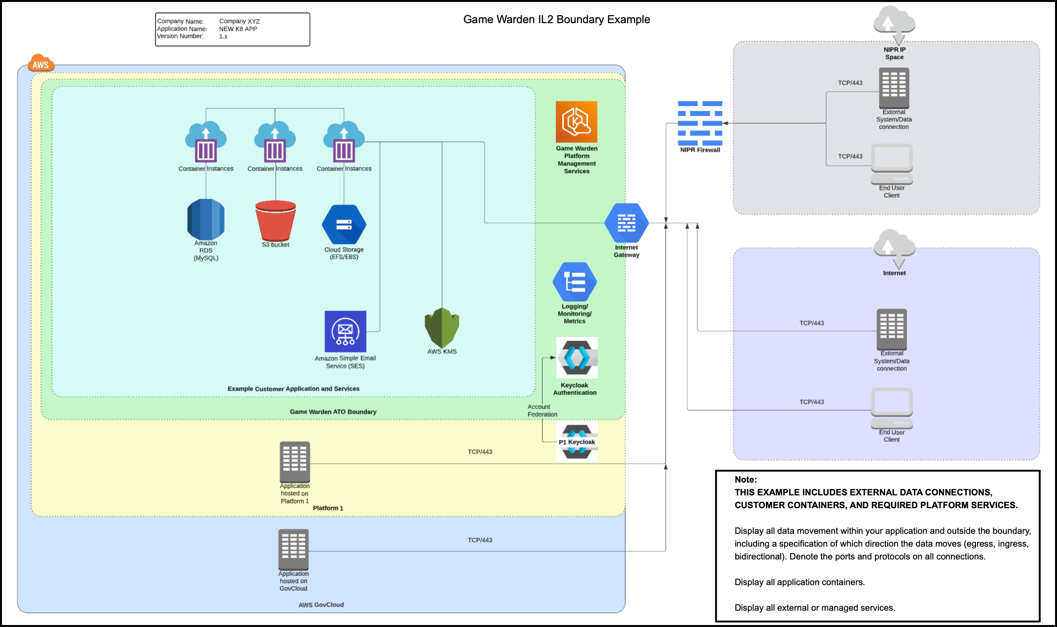
The following diagrams illustrate how external users access the Game Warden environment. On the right side of each diagram, you’ll see two types of users:
- One accessing through the Department of War (DoW)’s Non-classified Internet Protocol Router Network (NIPRNet)
- Another accessing via the public internet
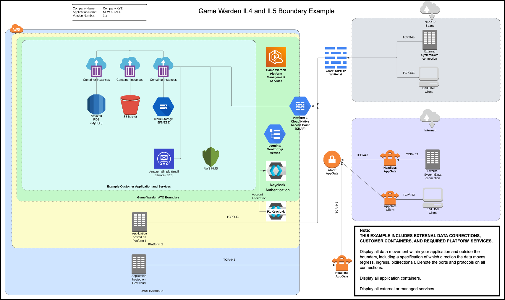
At higher Impact Levels (IL4 and IL5), access is controlled through a CNAP/BCAP, which does not exist at IL2. This is the primary difference between IL2 and IL4/IL5 environments. CNAP/BCAP uses an IP whitelist to screen NIPRNet users, allowing access only from approved DoW IP addresses.
Once screened, both NIPRNet and public internet users route through an Internet Gateway to reach the Game Warden Authorization Boundary. From there, they can access AWS services and application containers.
All customer environments are protected by Keycloak for authentication. For applications hosted on Platform One (P1), users must log in with P1 credentials. CNAP/BCAP also acts as a gatekeeper for P1 access at IL4 and IL5.
As shown in the diagrams, external access to the system may involve the following paths:
- NIPRNet
- Public Internet
- P1
- AWS GovCloud
The diagram below displays the external data connections, customer containers, and the required platform services.
The diagram below displays the external data connections, customer containers, and the required platform services.
Note
- If your Virtual Desktop Infrastructure (VDI) is on NIPRNet, you can access IL4 and IL5 environments without using Appgate SDP, the DoW-approved authentication service.
- If you are not on NIPRNet or using a NIPRNet-based VPN (such as Air Force Desktop Anywhere), you must use Appgate SDP to access IL4/IL5 applications on
afwerx.dso.mil. This is a DoW P1 team requirement. - For AFWERX customers: Show CNAP in your diagram (base environment: afwerx.dso.mil)
- For DISA customers: Show BCAP in your diagram (base environment: 2F.mil)
Need help with creating your diagram or have questions about your architecture? Reach out to your Mission Success Manager (MSM).